few questions

Discussion on Stirling or "hot air" engines (all types)
Post Reply
cabanaboy
Posts: 2
Joined: Mon Jun 13, 2011 7:27 pm

few questions

Post by cabanaboy »

I've been working on designing a Stirling engine over the last couple of days and I am having trouble figuring out a few things.

After plugging in a series of temp differentials and conceptualizing in my head it seems to me that optimal stroke and bottom dead center are variables of RPM, hot and cold side temperature. Is it plausible to instead have a free floating piston drive a rotary vane motor through check valves?

how can I calculate the heat transfer between air and aluminum with a static surface area over time? I'm sure there is a experimentally derived K factor in there some where. If I could calculate the exact heat per mole of air at any given time during a cycle at any RPM and temp differential it would make designing this thing a lot simpler.

whats the typical natural frequency of small off-the-shelf check valves? having built in check valves makes the piston cylinders a lot more complicated and I would rather just plug them into hose barbs.

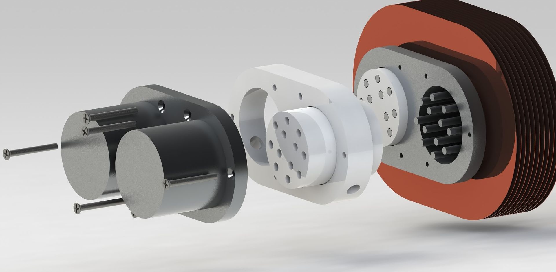
my displacer (photo below) has a much higher surface area to volume ratio than normal. Because of that it's possible to have a tighter fit and run at the same RPM's as a standard displacer before running into trans-sonic flow and compression. However, is there a minimum gap requirement? I'm worried that i may run into issues with a small gap to area ratio because of mechanics that I am not aware of.

I'm not an engineer I just have a GED and Wikipedia so please no flames. I'm hoping someone here is so they can help me understand this all better.

Image
and yes, you can solder copper to aluminum, it just takes a bit more effort (it does corrode over time though).
Ian S C
Posts: 2218
Joined: Thu Dec 02, 2010 5:15 am
Location: New Zealand

Re: few questions

Post by Ian S C »

Cabanaboy, I imagine that you have read a number of the books available, and built at least a few motors to a conventional design, you should do this before heading off into the unknown, its easy enough to get lost without complicating things.
Now, what is your displacer made of? he rods that pass through the displacer, are they attached to the hot end of the hot cap, and what is the hot cap made of?
You could have a free piston coupled to a smaller piston as a compressor. The compressed air driving the rotary vane motor, but I don't think it too practical.
Don't know too much of the maths on heat conduction. Ian S C
cabanaboy
Posts: 2
Joined: Mon Jun 13, 2011 7:27 pm

Re: few questions

Post by cabanaboy »

The rods that pass through the displacer are not attached to anything (machined into the heat sinks); there is a 2/8" gap between the rods on the cold side and hot side. The displacer is only in contact with the control rod and makes no contact with anything else inside the chamber. The render shows the displacer modeled in ceramic. I want a material with a very low thermal conductivity in order to maximized the temperature differential but I'm worried about it's failure mode, mass, working temp and thermal expansion so I'm not dead set on anything like dental plaster yet. I am going to use dental plaster for the spacer between the heat sinks though so it just made sense.

Using a piston set up how you explained would be very inefficient. as you compress the air more you decrease flow rates and lose more energy because part of the work put into compressing the air goes into needlessly heating the air on the rotary vane pressure side also. Basically even though the pressure is higher you end up doing less work. It's better to just have a single piston free floating feeding the rotary vane with a higher flow at lower pressure. even at one atmosphere though the pressure equals about 14-15 PSI; so with two pistons (one on compression and one on vacuum stroke) the observed pressure on the rotary vane would be around 28- 30 PSI (Assuming static flow, stalled rotor). AS RPM increases the pressure drops while flow increases and efficiency should increase also up to a point. The Idea is to favor flow rate while avoiding pressurization; I know that seems strange at first.
Ferraccio
Posts: 188
Joined: Thu Jan 27, 2011 10:57 am
Location: Italy

Re: few questions

Post by Ferraccio »

Cabanaboy, my English is very poor:
First, know what others have done, (and where they went wrong, if they are generous enough to tell you ...).
Second, try to build something that works.
Third, build something that works better.
Fourth: to invent.

I think you do not have read:
"Making Stirling Engines" by Andy Ross.
..about his experiences in past years, and the use of the technology.

Also I have tough and proposed to use porcelain or ceramic, have to be considered the advantages and disadvantages.
Ian S C
Posts: 2218
Joined: Thu Dec 02, 2010 5:15 am
Location: New Zealand

Re: few questions

Post by Ian S C »

A stirling engine has a fixed amount of air alternately heated(expanded) and cooled (contracted), there is no apprecialflow of air that could be used to drive a turbine (which at low pressure would require a large volume of air). If it did work at all the efficiency would be very low, an unpressurised motor would do well to better 5%. Even diving a generator from the crankshaft of an atmospheric pressure motor is an inefficient means of poducing power, little generators are usually about 50% efficient, and I think the turbine would be less, then it's got to drive something. Ian S C These are only my ideas, I'm quite possibly wronge.
Post Reply