I've been spending a lot of time trying to figure out / design a regenerator that could be used in a simple LTD type engine. Here is what I finally came up with, though I haven't built one or tried it yet. I'm also wondering if something like this hasn't been thought of before.
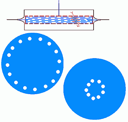
The idea is to make the air flow between a stack of closely spaced, probably very thin stainless steel disks. Some sort of diaphragm around the sides to insure that the air passes through the disks and not around the sides of the displacer/regenerator.
The disks would have holes as illustrated, offset so as to force the air to flow between the disks. Other configurations are possible, just as long as the air will be made to travel between the disks to get from one layer to the next.
It's funny, the things that keep you up all night. Some 9" pie plates and silicone rubber cooking pans are still on the counter where I was fooling with this very thing. Except I was thinking just one metal plate on the displacer hot side, with the matrix material between it and the perforated diaphragm. I think an all-diaphragm engine is the way to go, but the pie-pans are only an interesting distraction until I can figure out a good arrangement. It looks like you could put a rubber baking pan inside a pie-pan chamber for a displacer/regenerator, and put another rubber baking pan upside-down over all of that as a power diaphragm. They fit pretty well. Other pie-pan bits could make up the diaphragm plates. I'd leave the center of the power diaphragm flexible to connect to and drive the displacer as a ringbom. Looks like there's enough flexibility for a pie-pan beta Stirling to get 1/2" power stroke and 1" displacer stroke - about 15 cid - though that might give too much compression for the relatively low working temperature difference. The silicone rubber baking pans should be good for 500 f and the power diaphragm would be cooled by the pan on top. You could add a fan, but the oscillation might provide enough turbulence on its own.
If anyone else wants to pursue this in an open-source power-to-the-people kind of way, it'd be interesting to compare notes.
One thing about the displacer/regenerator - I think silicone is actually a fairly good thermal conductor so insulating the two sides from each other might be in order. I was wondering has anyone tried fiberglass insulation as regenerator matrix?
Edit: I stated my orientation of those baking pans wrong. Both rubber pans are upside-down on top of the pie-pan chamber, and the displacer/regenerator plate is on its top side, since it has to push it down into shape. I need coffee.