Heat Exchanger Design
Re: Heat Exchanger Design
Andy Ross found that, for small engines, stainless foil/shim stock with dimples, or creases made the best regenerator material. Ian S C
-
bladeattila
- Posts: 44
- Joined: Wed Aug 21, 2013 10:31 pm
- Location: Budapest, Hungary
Re: Heat Exchanger Design
Yes!
The foil is a perfect regenerator for other type of hot air engine, but the thermal lag has big different on P-V diagram as Stirling's P-V. The cycle is different. The working method a little bit similar as the pulsejet. The stack here is not a really regeneartor, or not just regenerator, because there is a tube what connect to the power cylinder (cold side).
https://docs.google.com/viewer?a=v&q=ca ... C7Sl-UyhMQ
It could be a new phisical essay, but my english is not enough yet for this, so I linked it.
I think the first step to understand the work of this engine.
The original Tailor patent isn't use regenerator, just small diameter tube.
The new type thermal lag engine has a long, small diameter tube. My opinion is the gas regenerated in there, and not in the stack! The stack is a high surface heat exchanger, but some people's opinion is, that last section (after the stack) should be cold or medium temperature, because the compression is easier on colder temperature and then this stack working as a regenerator too when the gas going backward.
Last edited by bladeattila on Sat Aug 24, 2013 8:45 am, edited 1 time in total.
The flames of ignorance doesn't hurt when you burn.
-
fullofhotair
- Posts: 265
- Joined: Sun Aug 05, 2012 6:28 am
Re: Heat Exchanger Design
How about using thin sheets of metal stacked ,with a tiny gap between each one. You can get copper foil ,even gold foil. I dont know how you would keep them seperated. Maybe even a composite of different metals.
Re: Heat Exchanger Design
as far as thermal lag goes I have found that once the engine gets up to peak operating temp it begins to slowly lose power. cooling the cylinder results in more power loss and it begins to run better after the cylinder warms up again. I see it as a balance of hot on one end cool on the other end and warm in the middle. When the engine is cold and you begin to heat up the hot end even though the exchanger is red hot the heat tube and cylinder are still cold. When you try to start the engine it shows response but will not run until the rest of the heat tube reaches a certain temp. Until this time the air is being cooled before it reaches the cold cylinder. You want the air to stay hot until it reaches the cylinder. Once the engine begins to run the heat tube continues to heat up due to the extremely hot air flowing through it. At one point the engine reaches it's peak performance (perfect balance of hot, cold and warm in the middle). Now the engine runs good for a while but begins to slow and lose power. Notice that the heat tube is getting very hot and now it begins to experience premature heating. You now are beginning to get the opposite of what you started with. The warming cold side helps to keep the balance but if you cool the cylinder with water or ice you then get the complete opposite of what you started with, and that is cold cylinder with a very hot heat tube. The cooler air is heated to much before it reaches the heat exchanger. You want sudden heating and cooling. I think the connection between hot and cold side should be a type of tubing that does not conduct heat or store heat. This way the air is neither preheated or precooled. Also the tubing could be highly conductive with a series of heat sinks along its hole length to cool it somewhat so that it maintains desired operating temp.
I have noticed that the Ted Warbrooke design uses a copper tube to connect the hot and cold end. This tube could be dumping the heat into the surrounding outside air and maintaining a lower operating temp.
I have noticed that the Ted Warbrooke design uses a copper tube to connect the hot and cold end. This tube could be dumping the heat into the surrounding outside air and maintaining a lower operating temp.
Re: Heat Exchanger Design
Derwood, did you ever compare the regular steel wool again? - when the first exchanger disintegrated it might have affected piston performance for further testing.
I agree that the choke should have as little thermal effect as possible. I know thermal lag engines can be made to run using no more trickery than the sinusoidal piston speed from a normal crankshaft, but I think flow management is used in some to time heating for roughly the same effect as displacer timing in Stirlings. I think one purpose of the choke, along with imparting enough velocity to penetrate the wool at the end, is to introduce a clean column of air that's somewhat insulated from the heat tube by the more static surrounding layer of air. Of course the surrounding air would be compressing downward as the column is moving up, and at some point the column would fall apart and mix, hopefully near the end of the stroke. If the column could be maintained until its displacement was a bit less than piston displacement, heating would be delayed until near T.D.C.
Perhaps the same principle could somehow be applied in reverse at the cold end.
I've already been laughed at for this theory before, so don't worry about disagreeing.
Bumpkin
Re: Heat Exchanger Design
The piston already had some minor scaring from prior testing. It seems no matter what I use some small debris always ends up in the cylinder. I went back to stainless scrubber and performance was the same as before. I am going to make a new exchanger with even thinner stainless tube. The engine ran well before compression increase. I think it is set good now for heat exchanger testing. Once I am confident my heat exchanger is as good as possible I will move on to the other issues. After seeing how much power it is capable of, (regular steel wool) It is out of the question to lower compression again. I can be very stubborn sometimes. LOL!
Re: Heat Exchanger Design
For the hot end you can go to between .010" and .020" wall thickness with stainless steel tube, good wee job on the lathe, put a mandrel inside the tube, take it at a slow speed, but force the cut along quite rapidly, some stainless machines better than others, you probably know that, but others may not. Ian S C
Re: Heat Exchanger Design
I have the hot end ss tube turned down to .025. I still have to pu it back together and test it.
Re: Heat Exchanger Design
I am happy to say that my problem was heat exchanger design. Originally the inner tube stopped about 3.5 inches away from the end of the outer tube. The last 3.5 inches of the outer tube was thinned and filled with ss wool. It worked good on lower compression but when I increased compression the air did not flow freely into this area. I think the air immediately turns into the inner tube as soon as it reaches the end of the inner tube. Basically the leading edge of the heat exchanger was the only section doing any heating. Air was not flowing into the rest of the exchanger. I cut down the outer tube and now it extends past the inner tube 1/2 inch. This half inch area is filled with ss wool. Cutting down the outer tube raised compression even more but the engine runs smooth. The last two inches of the outer tube is thinned to .025 and the ss wool fills the last 1/2 inch of the outer tube. Compression is now at 2.6 to 1 and the engine does not struggle at all. I am confident I can get it close to 2:1. Now I am trying to find a 12 volt motor to test power output. I tried a 12 volt 250 ma motor but my crank pulley was to big and the motor was turning at about 6000 rpm. It seized in a matter of seconds. I need one capable of about 12 volts and one amp. Need to change to a smaller crank pulley or larger motor shaft pulley.
-
bladeattila
- Posts: 44
- Joined: Wed Aug 21, 2013 10:31 pm
- Location: Budapest, Hungary
Re: Heat Exchanger Design
Hi Derwood,
If you can make a little shaped cone to the hot end SS tube, then the air could to move easier into the regenerator.
The heat contact surface will be higher then with flat end much more.

If you can make a little shaped cone to the hot end SS tube, then the air could to move easier into the regenerator.
The heat contact surface will be higher then with flat end much more.
The flames of ignorance doesn't hurt when you burn.
Re: Heat Exchanger Design
bladeattila wrote:Hi Derwood,
If you can make a little shaped cone to the hot end SS tube, then the air could to move easier into the regenerator.
The heat contact surface will be higher then with flat end much more.
What software are you using for your drawings?
Thanks!
Re: Heat Exchanger Design
Although that would work good for my engine, My inner tube comes to a point at the head and the outer tube carries the air back and forth. There is a 3/16 in. gap between the inner and outer tube. With the increased compression I now realize that it needs a cooling system badly. When it gets to hot to run, I can let it set for about ten seconds and it takes right back off again but only for a few seconds. cooling the cylinder makes it worse. Cooling the heating tube brings it back up to full power. Cooling it too much makes it lose power. I might try an air shroud and cooling it with a small fan powered by the engine. I discovered that when it is hot, letting it set for a few seconds allows the heat tube to cool a bit. So maybe with some fins welded on length wise and a shroud around them with some air being pushed through might regulate the temp. I will be mounting this to a rocket stove that I have been heating my garage with. I might pipe the air intake of the stove so that it is pulled through the shroud. this would eliminate an engine powered blower.
-
bladeattila
- Posts: 44
- Joined: Wed Aug 21, 2013 10:31 pm
- Location: Budapest, Hungary
Re: Heat Exchanger Design
I used paint for drawing, this is a simple program for shematic plans.
Than your engine is similar for this:
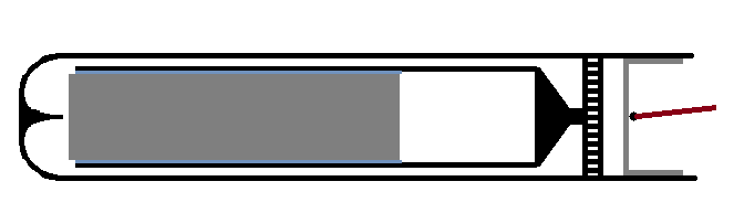
Than your engine is similar for this:
The flames of ignorance doesn't hurt when you burn.
Re: Heat Exchanger Design
Yes, it is similar. I would like to clear up a few statements I have made about my thermal lag engine. For anyone who has watched the latest video, I am sure you noticed the big square steel heat break. On earlier models I could not get the engine to run without it. It was compensating for something I guess. I removed it and the engine ran much better without it. Now it is responding like a heat engine should. Cooling the cylinder now increases power, where before there was a power decrease. Cooling the heat tube no longer increases power.
Re: Heat Exchanger Design
That was confusing me Derwood. one of my videos shows what appears to be a slow down when appling more heat before it did increase rpm. After your post I was trying to understand the dynamics of such. Have a look at the video Im speaking of...
https://www.youtube.com/watch?v=5TycrOca7sk
Even tho its not a true alpha engine like yours Im guessing, wouldnt the principles be the same?
https://www.youtube.com/watch?v=5TycrOca7sk
Even tho its not a true alpha engine like yours Im guessing, wouldnt the principles be the same?
What we need is a More Heat or More cold, and Less Friction or Better Air Seals ...and an Aspirin!
Sripto Vu-Lighter Historian http://www.thehawkeco.com
Sripto Vu-Lighter Historian http://www.thehawkeco.com