Are there any electronics guys (or anyone) out there that can help on this one??
What I’m thinking of is the correct design of a 'Maximum Power Point Tracker' (MPPT), for trying to find the sweet spot in any Stirling engine that is driving a generator. (The ideal output RPM). With the right MPPT regulator, (bye its nature) the best dynamic output of any engine at any varying temperature would be located, resulting in maximum power generation. This could save a lot of testing and fiddling around trying to find the right load and torque and RPM relationship.
There are wind/hydro MPPT regs on the market but i'm not sure that they would work on Stirling engine powered generators to track and hover around the right RPM output (they might stall the engine).
Has anyone got any thoughts on this?
vamoose
MPPT for Stirling Engines
Re: MPPT for Stirling Engines
Vamoose, to find best power, you need a rev counter, a brake to measure torque, depending on what tachometer you use, a stop-watch. You then need a graph, and take a number of readings at different revs by loading the brake,(I use inch ounces), I hope soon to have digital scales ot measure with, instead of a weight on an arm, and a non-contact, digital tacho, instead of the home made mechanical one I have now.
You could also hook up a little electric motor, to run as a generator, and put a load on the that can be varied, it needs two meters, a volt meter, and an amp meter, amps X volts = watts. If your lazy like me, you need a calculator for either method. Ian S C
You could also hook up a little electric motor, to run as a generator, and put a load on the that can be varied, it needs two meters, a volt meter, and an amp meter, amps X volts = watts. If your lazy like me, you need a calculator for either method. Ian S C
Re: MPPT for Stirling Engines
Thanks Ian its probably the most practical and available method,
Although, the testing process is what I’m indicating could be avoided. As I mentioned the engine would have to be driving a generator that is running through the mppt reg (this would then be charging a battery). The mppt uses Pulse Width Modulation (PWM) and adjusts the space Mark ratio to vary the load and tracks the optimum available power on a volt amp curve, by taking sample rates whilst adjusting slightly the mark space ratio and monitoring the feedback (with inbuilt software and smarts)(at least this is my understanding of how they work). Although a fairly recent development mppt's are used in all the solar grid connect and many of the stand alone solar systems I install. I'm yet to use one on any wind turbine and micro hydro systems (they're a bit pricey for generators), but I think on the next one, I might look into it.
vamoose
Re: MPPT for Stirling Engines
Hello Vamoose,
I know almost absolutely nothing about building a Stirling engine, but have done motion controls and designed control systems for over 25 years. I suspect the type of control algorithm your MPPT would want to use is not much different than the “dither and lock” controllers I have created for lasers; optimizing the laser efficiency/power by optimizing some parameter (crystal temperatures, cavity lengths, etc.). I suspect the Power (Y axis) versus RPM (X axis) would look somewhat like an upside down “U” or a bell shaped like curve. If this is correct, then a dither and lock technique would be ideal for your trickle battery charger. This kind of control will automatically correct and find the best battery charge current (RPM and output power) as the temperature or performance of a Stirling motor changes. Here is how a dither and lock works…
As Ian pointed out, you will need a volt and current meter to measure power out of your generator. RPM data is not needed, but might be nice for controller to know if Stirling is stalled and trigger an auto-start off the generator. This data can go to a microcontroller (easiest to implement) or discrete analog circuitry for the controller (I’ve done both). But ultimately it must be able to control the power of the charger to your battery (or load) and thus the speed of the motor. For example, a 0% duty cycle on a PWM charger would be 100% RPM of the motor. Likewise a 100% PWM on the charger would more than likely result in 0% on motor RPM. The “OPTIMUM” is somewhere between!
The idea is that you increase (or decrease) the charging PWM and measure the power delivered to the battery or load. Depending upon what side of the Power –vs- RPM curve you are on, the increase in PWM will result in an increase or decrease in power measured, or no change when at/near the peak efficiency.
For example at low PWM duty cycle for the charger, a Stirling motor will be at or near max speed, but the power measured will be lower than optimum. Increasing the PWM slightly should result in an increase in measured power, and a slight decrease in charging PWM will result in less power delivered. This will continue up to the OPTIMUM point. Once past the OPTIMUM, an increase in the PWM duty cycle will result in a decrease in output power, and a decrease in PWM duty cycle would increase power. Please note the sign change once past optimum!
This increase and decrease in the PWM is the “Dither”. So how do you do a “LOCK”? If you mix the dither signal with the power signal (fancy word for a multiplier!) you get a resulting error signal that can tell your PWM what way to drive. An integral based control law would then control the PWM duty cycle up/down to maintain optimal performance from the motor. Each motor would have to be tuned and dither amplitudes determined. But once that is done, it should control the motor nicely, just like it does for my lasers…
Hope this helps, we can discuss more if interested…
-J
[hr] If crime doesn't pay, does that mean my job is a crime?
Re: MPPT for Stirling Engines
Thanks NerdyEE,
'dither and lock', so that’s what the process is called. The way you explain it makes sense to me that it would work as required. Maybe generator mppt's on the market use this process and would work on a Stirling engine driven generator, but i suspect there are load responses (mark space ratio variations) that are specific to Stirling engine sensitivity, that need to be programmed/considered. I will have to take time to read your post in a bit more detail to take it in properly, but I’m think we're on the same page. Thanks for your knowledgeable feedback, its really helpful. Electronics is definitely one of my weak points.
vamoose
Re: MPPT for Stirling Engines
The old system for petrol(gas), chargers/ power suplies was the battery voltage dropped in use, when it got to a pre determand level, a relay dropped out, and the battery switched to the generator causing it to motor over, starting the petrol motor, when the revs came up the generator started charging, and continued until the battery was up to charge, and the motor was shut down, all automatic, and no electronics, just relays. Could be done electronicly, and give a more scientific charge rate, could even be designed for Lithium batteries. Ian S C
Re: MPPT for Stirling Engines
Most Stirlings have a torque rise as R.P.M. drops that would approximate the amperage rise of P.V.s as voltage drops. If the Stirling alternator freewheels at a comparable voltage to an open circuit panel, a M.P.P.T for photovoltaic charging MIGHT work right off the shelf. Bumpkin
Re: MPPT for Stirling Engines
Hello again guys,
When I first read this and responded to the post, I hadn’t read anything about MPPT controllers. They are not what I describe! From what I just read on MPPT controllers for solar, these are simply DC-DC converters that try to match the photo cell optimal voltage (17V) to the optimal voltage for a battery (12V). Think of them as a fancy transformer that matches the source and load to get optimum performance from both. Again this is NOT what I try to describe as the optimal controller for a Stirling with the “Dither & Lock” method…
There are many other control laws or methods that will work to optimize the power output of a machine or process. Ian points out that “Bang-Bang” control with a relay can possibly do the job. Alexandr Fediaev does a great job controlling his Alpha Stirling Bang-Bang style. See: http://www.youtube.com/watch?v=OOVbsIFyJD8 He even has a Power –v- RPM diagram at the end of the video that shows the bell like curve I suspected. Again there are other methods, I only suggested this one as it is simple to implement and I believe it would work very nicely for what Vamoose was requesting, or I believe he was requesting…
Where my idea and the MPPT are common is with a DC-DC driver. I called it a PWM battery charger with a duty cycle. Said PWM will charge the battery but unlike the MPPT doesn’t really care too much what voltage the Stirling and generator combination offer as voltage for the battery…
Please note, I never mentioned ANY ELECTRONICS or implementations other than digital or analog. I simply was trying to suggest a method to resolve a problem and how it works (big picture). We can discuss electrical details and implementations if so desired. The Arduino chip you mentioned in the “BIG STIRLING” post would be an excellent candidate for this. You do not need major computing power, and if you can do this forum formatting and embedding, you can program it well enough. I also didn’t mention the frequency of the dither and other critical details for good reasons…
Let me know and we can start forming some building blocks of the controler and start exploring some details on each. Tonight, I suggest the PWM Battery Charger as I suspect this is the “Mark Space Variations” topic mentioned by Vamoose. This PWM charger PWM frequency would need to be high, say in the 20KHz or higher frequencies (above the audible or you hear it!). The Stirling will not be able to react to this high frequency, looking like a low pass filter and thus averaging the PWM draw. Yes it has a power relationship with the motor, but is going to be our control point for the motor speed (how we impact it); more PWM % will result in a slower RPM. Our changing of the PWM% will be our dither, and this frequency will need to be below the natural response of the motor under test…
Enough for tonight mates, I need to go to bed…
-J
[hr] If crime doesn't pay, does that mean my job is a crime?
Re: MPPT for Stirling Engines
Yikes! Ok so I am officially and very quickly way out of my depth on this topic. (like I am on many). But I am getting the gist of it in small increments.
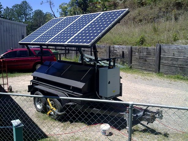
I have used MPPT's in systems I have made. But I'm not really familiar with their inner workings.
Here's a portable system I made to power my shed that uses a MPPT reg for charging.
Bumpkin if the open circuit voltage window was adequate (it might need to be quite high though) then maybe an off the shelf solar mppt would work, but i'm wondering now, if it would find a Stirling engines sweet spot, I’m not really sure any more. But it may well do so???
NerdyEE it seems like you might have your finger on the pulse on this subject, so if you think there is any potential to it then feel free to give your 2 cents worth. It honestly is not my forte and I am only a passenger. (I realise there are probably more important things at hand, ie- the making of actual Stirling engines)...
I often look at a lot of these kinds of devices as a black box (my poor noggin is easily overloaded), there may be a gerbil on a hamster wheel in there for all I know, or even Schrodinger's or some other poor worried souls, lost (potentially dead, potentially not) puddy tat.
If a little bit of knowledge is dangerous then I’m definitely in danger.
But all wisecracks aside I will try and summarise my thoughts on the subject
My suggestion is based around locating the best power output of a Stirling engine, but not trying to charge a battery specifically.
I think it is possible to find, the best load/rpm relationship of the Stirling engine along with the best voltage and amp relationship for any connected generator relative to its wire diameter and number and size of the windings.
for example (something I'm a bit familiar with) for a micro-hydro 'stream engine' you have to first find the right water flow rate and pressure (this determines force on the blades and the most efficient rpm) and then match the best winding set-up of the generator, that is best for the battery voltage that you are trying to charge. They can be connected parallel delta, parallel star,, series delta or series star. You do this with tables that have been developed, but it is never an optimal output, it's a compromise.
I think the same system dynamics are comparable to a Stirling engine. So if you had a regulator that dynamically allowed any generator to work in its best volt and amp range, whatever its winding set-up, and load and rpm (and whether it be dither and lock method or some other method), then the device driving it may by default also work in its best range.
This regulator, if possible to be made, is not something I would currently be able to use, as I haven't even made a genuine Stirling engine that would even qualify for the use of one (at least so far, i'm hoping to change this one day).
But if such a device was available then I think it would come in very handy for the more serious Stirling engine maker to easily find their optimal engine output relative to a whole lot of variables.
I'm really just putting the topic out there at the moment to find out peoples thoughts and for anyone who may find it interesting. Hopefully, eventually i will have the need for one..
vamoose
Re: MPPT for Stirling Engines
Holly smokes Vamoose, I feel more like I am way out of my league here. With that solar setup you got, you are serious enough, and also well written/spoken. You truly hit the nail on the issue of using a solar MPPT with a Stirling; it can’t/won’t optimize the RPM & Torque. Solar is basically a constant power, you can’t alter the source other than heliostat control. It doesn’t have a bell shape output power curve, very linear (light in, power out). So you get what you get and you don’t throw a fit. What the solar MPPT does is take the wide dynamic range of the solar voltage output due to solar irradiance input and keeps the voltage constant to the next load, be it a battery charger or an AC inverter. This is **EXACTLY** what you did with your steam generator when you matched your windings to the battery…
Feel free to get a solar MPPT (I see them at Digi-Key, Mouser and others) and try it! What I believe the solar MPPT will do is take what the Stirling will give for voltage and match it to the loads desired voltage. If the load requests more power, it will tax the Stirling until the Stirling stalls if power requested is greater than engine can deliver. The Solar MPPT will just try to keep what voltage is provided and do a DC-DC conversion with regulation to keep its output voltage constant. By the way, we may want one of these building blocks for your Stirling motor power optimization controller…
So first things first Vamoose, this is your baby. What do you want to call this thing? Stirling MPPT or what? Personally using “MPPT” may confuse things…
I am more than willing to continue this discussion with you (publically or privately) and if provoked properly even make a mock-up of this with a toy Stirling I bought with a pulley wheel. I think this motor would make an excellent demonstration of the controller and concepts. I tried to connect a small motor to it but would stall the motor with the loads I was trying.
So I think with the above discussions we have pretty much fleshed out the concepts needed for a PWM output stage that controls the Stirling RPM. It would take the power from a Striling Engine and Generator stage and control the power delivered to a load; be it a battery charger or an AC Inverter supplementing a home power. The PWM stage may need a MPPT like device (DC-DC conversion stage) to optimize the transfer of power (whatever voltage and current) to one that’s voltage or current is more regulated. Said PWM stage is what will be used to control the RPM of the Striling. The assumption here is that as the PWM duty cycle percentage increases, the Stirling motor RPM will proportionally decrease. If this relationship is not true, then the control will not operate as I outline…
So have we flogged the PWM stage enough? We will go to implementation later after all block have been explored…
I propose our next discussion be further exploration on the input signals and what processing will need to be done to get a dither and lock working… (ok?)
Cheers,
-J
[hr] If crime doesn't pay, does that mean my job is a crime?
Re: MPPT for Stirling Engines
Hi Again Vamoose!
First off, I apologize for taking over your posting here with my babble. Feel free to tell me to stop…
I decided that tonight (my time) I would write about the signal processing needed to generate an error signal that would be used to drive the PWM stage duty cycle percentage to optimal duty cycle and thus optimal RPM/Torque => Power out. Sorry for jumping around, but for me, this section is the most interesting part!
To do this I looked at all of the math tools I had, but decided all users must have access to the tool. So I created a small little Excel sheet to simulate what we should see and the resulting error signal. See attached file. Please note this forum doesn’t allow Excel files. So I stuffed it in a ZIP file... The Excel sheet allows you to adjust the amplitude of the Dither, the AC coupled Power signal (will use a DC blocking filter to let Dither frequency pass) we will obtain from Current and Voltage measurements, and its phase (0 or 180; but exploring with other values is fun!). I started to make this overly complicated (Voltage and Current => Power with individual phases), but realized I am not that good at Excel and the net results would be the same with what I generated. Just have to remember that there is extra “POWER” signal processing required.
So updating the Excel sheet input parameters (in green highlight) will plot the Blue (Dither) and Green (AC Power) curves in the chart. It will also plot the result of multiplying the Dither and AC Power signals together (Mixer). The result is a full wave rectified signal shown in Red. Play with the amplitude of the Dither, what happens to the Mixer? Play with reducing the Power amplitude to simulate how the amplitude will reduce as we near the peak of the RPM/Power curve.
[album]81[/album]
So once we are beyond the optimum operating point, the phase of the power will go 180. Note the Mixer signal is now full wave rectified but negative! Play more with the Power amplitude. Have fun!!
[album]80[/album]
This Mixer signal can then be sent to a compensation stage integrator to drive the base level Dither duty cycle percentage to the optimum point.
Cheers,
-J
[hr] If crime doesn't pay, does that mean my job is a crime?
Re: MPPT for Stirling Engines
NerdyEE/(J), Please don’t for one second think that you’ve taken over this discussion. I am totally stoked that this topic interests you, and that you wish to be involved. (It also intrigued me, that’s why I raised it.). I think you’re skills are just what the doctor ordered. I really appreciate the effort you have made.
Feel free to evolve the discussion in any way you wish, my input may be light at times (mainly because its way more heavy than I expected it would get, and I’m definitely in catchup mode (plus other time things)), but please just put it out there, I’ll try and give a more respectable contribution to your posts once my head stops spinning.
I expect the regulator requirements that have been discussed are feasible, but I will have to dig back into the annals of my books and mind to re-familiarise myself with a whole lot of stuff, (that I never really knew in the first place anyway).
I am definitely going to have to read over this topic and its posts, several times, (and do a lot of googling).
Also Ian and Bumpkin, again, when I get the the time I’d also like to discuss some of the points that you have raised in more detail. I know both of you to be very Stirling engine savvy and I have more than a few questions, that I know you guys can help me with, on the topic...
vamoose
Re: MPPT for Stirling Engines
Hi Vamoose!
If you have any questions, PLEASE ASK! I entered this forum largely due to this/your post. Yes I have interest in this topic and will now continue to experiment with the concepts discussed so far and show a working model of the “Vamoose MPPT”. As I have mentioned before, I am an EE and not very likely to be machining my own fine engine like I see others here have done. I had so many ideas 4 months ago when I got fully inflicted with this disease; this forum, Google, YouTube, and many patent researches have shown they were EXCELLENT ideas, so much so others thought of them too! So if this exchange can help the community and hasn’t been done before, I’m all in! It will also allow me to use this discussion forum to educate the next Ph.D. Intern we take in that doesn’t understand Dither & Lock! So your questions and understanding are **VERY** important to me. If you don’t understand a concept, let’s explore it in the forum or independently. My email is my moniker at gmail. The stuff discussed so far isn’t rocket science; just a simple multiplication of two sine waves and a PWM stage. My posted Excel tool has two tabs (please try it!); one to enter data and see the plotted results, and a second tab for the actual data tables and calculations (creates the data for the plots; to see the math yourself). For the result in RED (the Mixer) I simply multiplied the Power and Dither signals together. It really is that simple!!!! Analog multipliers are a dime a dozen (we need two; one for Power and one for Mixer)…
Last night, my DVD/VCR died so I may have a source for a small motor to start some experimenting. The first experiment will be getting a generator (DC motor) connected to my simple toy SE (see photo below). I need it to prove that PWM Duty Cycle Percentage is proportional to speed. Then when I get the Big Stirling from Hyporex (FYI- got a shipping notification yesterday but tracking number is not being accepted yet as it is still in customs!), we can experiment on that one too…
[album]82[/album]
Do we need a block diagram to show where/how the discussed functional blocks tie together? Maybe that is why you are confused because I jump around too much… ;-)
Cheers,
-J
[hr] If crime doesn't pay, does that mean my job is a crime?
Re: MPPT for Stirling Engines
Found this while doing some googling, not sure but it looks like it could have some helpful info for this discussion. It's about a free piston control sytem:
http://www.ansoft.com/workshops/aeroee/ ... _regan.pdf
http://www.ansoft.com/workshops/aeroee/ ... _regan.pdf
If I seem argumentative, I apologize. I like to explore many sides of an issue.
I love to be shown I'm wrong, after all, Dad always said to learn from my mistakes!
I love to be shown I'm wrong, after all, Dad always said to learn from my mistakes!
Re: MPPT for Stirling Engines
Thanks Jerry! That kept me busy this evening. I learned more about free piston SE and dynamics. There definitely are some similarities. But it looks like this beasty wants to operate at a fixed frequency and amplitude or it will runaway to possible damage (?). Since they can’t control the radioactive heat source, they control the load to maintain an operation point they like best. Thus they have to bleed off excess energy they are not using to maintain that operation point. Still a very cool control problem so again, THANK YOU!!!! It is sad they used a PID control law and it shows on the responses to disturbances. I do much better on my lasers; I have to…Jerry wrote:Found this while doing some googling, not sure but it looks like it could have some helpful info for this discussion. It's about a free piston control sytem:
http://www.ansoft.com/workshops/aeroee/ ... _regan.pdf
-J
OOPS Forgot to mention that I harvested the VCR/DVD player and got 6 motors, and one that works nicely with the SE toy pictured above. I'm building some brackets to mount the motor to the toy SE that Junkie would be proud of (VHS bracket bent in vice). Will take a few more days (maybe a week) to get some basic motor data. Going to order a tachometer to see if we have the bell shape RPM/Power curve. Stay tuned...
[hr] If crime doesn't pay, does that mean my job is a crime?