Klein bottles are cool, aren't they. A friend showed me one a few years ago and I've always wished I was good enough at glass blowing to make one myself since.
I'm not sure one would be needed to set up a continuous Stirling engine, though. Surely you could set a Stirling circuit up in a similar manner to the Rankine circuits used in most power stations (http://en.wikipedia.org/wiki/Rankine_cycle)? The differences would be that the four parts the working fluids would pass through would be:
1) A turbine where the working fluid is heated throughout the turbine to keep it at constant (hot) temperature as it expands and drives the turbine.
2) A heat exchanger that cooled the working fluid at constant volume.
3) A compressor where the working fluid is cooled throughout the compressor to keep it at a constant (cool) temperature as it is compressed.
4) A heat exchanger that heated the gas at constant volume. After that the working fluid should be back to the state that it's in before phase 1) and you can cycle it around again.
Of course, the sensible thing would be to mount the turbine and compressor uniaxially, so that the turbine helps drive the compressor. You only really need one heat exchanger, too - you can pass the heat from the working fluid at phase 2) into the working fluid at phase 4)
Good luck getting that working IRL.
Stirling Turbine
Re: Stirling Turbine
this is hopfully a picture of a Liquid ring pump Stirling engine (stirling turbine
)
- liquid ring.GIF (10.12 KiB) Viewed 9656 times
Re: Stirling Turbine
Tom, I'm not sure that you can wring work out of a the air in the way that you originally described. The stage in which you extract work from the air using a turbine, making the air very cold, would also reduce the pressure of the gas to a very low pressure. When you came to exhaust the air back into the atmosphere you'd find that the pressure was below atmospheric, meaning you'd be sucking air in at both ends.
A similar situation is that for an overshot water wheel: The amount of work you can get from a water wheel is determined by the difference in height between the incoming and outgoing streams. Knowing just that fact, it would be tempting to dig the stream bed under your wheel a bit deeper and make your wheel a bit bigger. However, that would end up with the lower stream flowing back towards your wheel. Ultimately the stream levels are set by the surrounding topography.
In a similar way, the maximum work you can get out of the air around you is determined by the existing differences in temperature and pressure. There's nothing to stop you taking in air in a sunny area and exhausting it in the shade if you want to. However, the amount of energy you get out will ultimately be limited by the temperature difference between those two areas.
Re: Stirling Turbine
Dear Mr goat
get a grip , look up "liquid ring pump compressor" images and look at how they work .
compair this with the alpha configuration stirling engine stirling.
all the previous diagram is, is eight liquid piston alpha stirlings in a ring.
the alpha stirling works , the liquid ring pump works , BARBARA, the stirling turbine works.
Yours tom peat
Re: Stirling Turbine
Tom Peat,
Sorry, my post was in response to Tom Booth's original posts, rather than yours. I should have made that a bit clearer. My mistake.
Sorry, my post was in response to Tom Booth's original posts, rather than yours. I should have made that a bit clearer. My mistake.
-
DaS Energy
- Posts: 2
- Joined: Fri Dec 17, 2010 6:12 pm
Re: Stirling Turbine
Hello Tom,
Very much interested in your design. Can follow your thinking as I too have been working a hydro turbine hot air air engine. Plus the cooling of gas by stripping its pressure using a turbine then releasing the gas to expansion cooling.
My pursuit has included Co2 in place of air given its high pressure to heat ratio and its readiness to cool at loss of pressure.
Working test models to date have been Air, Steam and Co2.
No longer working model after upgrading to aliminium for lightness compared to galv pipe then discovering that Aluminium will not take direct flame.
That attached is simple hot air model.
Peter
- Attachments
-
- DaS One Peice.JPG (68.82 KiB) Viewed 9574 times
Re: Stirling Turbine
I don't think that would happen.goat wrote:Tom, I'm not sure that you can wring work out of a the air in the way that you originally described. The stage in which you extract work from the air using a turbine, making the air very cold, would also reduce the pressure of the gas to a very low pressure. When you came to exhaust the air back into the atmosphere you'd find that the pressure was below atmospheric, meaning you'd be sucking air in at both ends.
True, as the air exits the nozzle inside the turbine and the jet of air turns the turbine, there will be a drop in temperature. Pressure however should drop as far as 1 atmosphere.
How could it possibly drop any further than that when it is being exhausted from the nozzle into the turbine against atmospheric pressure ?
At any rate, theorizing one way or the other aside; existing Air-cycle air-conditioning systems routinely eject cold air "back to atmosphere" into some living space or other.
In studying such systems that use a similar set-up I have never seen any mention of any such problem as you describe. There is, as far as I know, no such problem or controversy surrounding the idea of using a turbine for cooling in the manner described. This aspect of the thing at least is in-use, proven technology with a wide variety of existing applications. There is no problem with any of these existing systems "sucking air in at both ends".
If anything I would think that the air, picking up heat from the bottom of the displacer chamber as it passes out of the system would tend towards re-expanding and building up pressure slightly above 1 ATM before exiting even if there were not a continual flow of additional cold air from the turbine pushing it along.
Stirling Pump
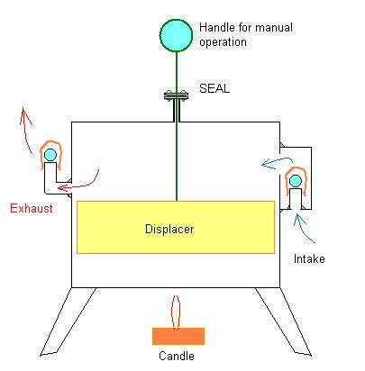
Earlier I posted this drawing of a hand operated Stirling-Type displacer chamber without any piston-cylinder, piston, connecting rod, flywheel or other additional apparatus to support all that:
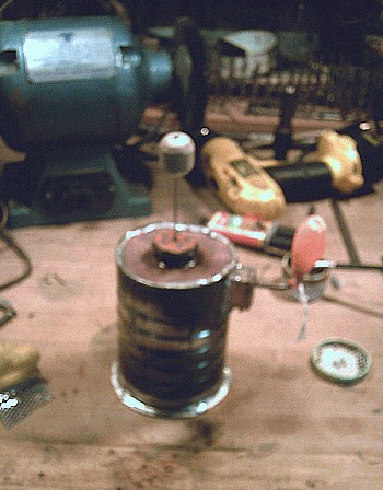
I also mentioned that probably the only way to figure out if this concept would work or not would be to just go ahead and build the thing and see what happens. Well, I have finally been able to secure a work-space (Shop) and have gotten as far as building a model of the above described "Stirling Pump".
I've had my interest in this project renewed recently due to happening across an old article by Tesla describing the theory of such an engine. Tesla himself worked on this idea for some time but eventually set it aside after his workshop burned down and decided to concentrate on what he considered work of a higher priority for him at that time. He apparently though, never stopped believing that such an "ambient heat engine" was a real possibility and in the article described the theoretical working of such an engine quite lucidly.
I will be testing this prototype Stirling -Type "Air Pump" which is one of the main components of this engine, and if I can figure out this camera, I may be able to take some short videos of it in operation. Working or not. (I'm still waiting for the epoxy to harden before trying it out).
Sorry my attempts at digital photography are not so good.
The first step, IMO, is just to see if such a "Stirling Compressor" can actually pump any air at all. If the theory is at all sound, even this crude "tin-can" model should at least be able to put some air into a balloon.
Hopefully I'll be trying it out sometime within the next few days. I would like to make a video of the "historic event" and let everyone know of the success or failure one way or the other.
If it isn't already clear, this model is just an empty coffee can - like a Stirling Engine displacer chamber equipped with two check valves instead of a piston, rod and crankshaft assembly.
The handle shown is to move the displacer manually.
Theoretically, if this thing is set above a candle or if it is set on top of some ice and the handle/displacer is worked up and down it should pump air through the check valves and into the balloon.
If it can do that much: create a linear flow of air, it should then be possible to use that flow of air to turn a small turbine, even if only something like a pinwheel at this point.
Anyway, I'll know more in a few days.
Tom
Re: Stirling Turbine
Well I succeeded in making a video, though the experiment itself was rather disappointing.
http://calypso53.com/stirling/Stirling_Ice_Pump.MPG (7.19 MB video file - MPG)
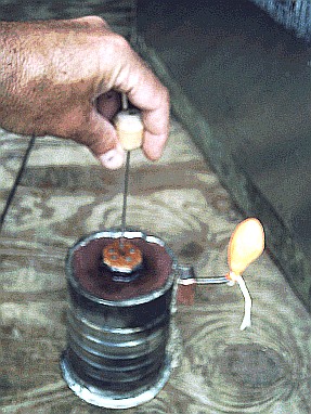
It appears the "pump" is putting some air into the balloon. The can is sitting on a bowl of crushed ice to create the temperature differential.
Unfortunately my rather crudely made "check valves" are not holding the air in the balloon as was intended.
The check valves consist of some old roller skate ball-bearings set on top of some narrow refrigeration tubing - the end of which was cut off with a hack saw and smoothed out as far as possible with a drill bit. This did not exactly result in an air tight seal apparently.
I would call the experiment a "success" to some degree in that obviously the balloon is expanding and contracting, the check valves are just not sealing enough to hold the air in the balloon.
Possibly a spring to hold the ball-bearing down and make a tighter seal would help.
I think, though that I will try making another model with larger metal plates on top and bottom for more surface area, more along the lines of an LTD type Stirling - and hopefully I can find or fabricate some more effective check valves.
http://calypso53.com/stirling/Stirling_Ice_Pump.MPG (7.19 MB video file - MPG)
It appears the "pump" is putting some air into the balloon. The can is sitting on a bowl of crushed ice to create the temperature differential.
Unfortunately my rather crudely made "check valves" are not holding the air in the balloon as was intended.
The check valves consist of some old roller skate ball-bearings set on top of some narrow refrigeration tubing - the end of which was cut off with a hack saw and smoothed out as far as possible with a drill bit. This did not exactly result in an air tight seal apparently.
I would call the experiment a "success" to some degree in that obviously the balloon is expanding and contracting, the check valves are just not sealing enough to hold the air in the balloon.
Possibly a spring to hold the ball-bearing down and make a tighter seal would help.
I think, though that I will try making another model with larger metal plates on top and bottom for more surface area, more along the lines of an LTD type Stirling - and hopefully I can find or fabricate some more effective check valves.
Re: Stirling Turbine
Hi, I'm sorry but I'm having difficulty understanding or following the workings in your diagram of the "simple hot air model". For example, you mention "direct flame" being a problem with aluminum. In the diagram, where would the flame be applied ?DaS Energy wrote:Hello Tom,
Very much interested in your design. Can follow your thinking as I too have been working a hydro turbine hot air air engine. Plus the cooling of gas by stripping its pressure using a turbine then releasing the gas to expansion cooling.
My pursuit has included Co2 in place of air given its high pressure to heat ratio and its readiness to cool at loss of pressure.
Working test models to date have been Air, Steam and Co2.
No longer working model after upgrading to aliminium for lightness compared to galv pipe then discovering that Aluminium will not take direct flame.
That attached is simple hot air model.
Peter
Testing new check valve
Using a neoprene washer (from a plumber's faucet repair kit) and a spring (from a ball point pen) I made some modifications to the one check valve that is accessible. (The other valve is soldered inside the bottom of the little copper box which is soldered on the side of the coffee can)
This upper valve, is, I think, the more important of the two valves which is supposed to hold the air in the balloon once it is captured.
Once the glue, holding the washer in place, dries, I can make another test and record the results.
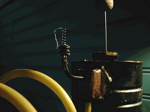
So far, testing the new check valve by using a tube attached to the lower check valve and gently blowing some air through the valves, there seems to be quite a bit more sensitivity and responsiveness as far as making an air-tight seal than previously.
This upper valve, is, I think, the more important of the two valves which is supposed to hold the air in the balloon once it is captured.
Once the glue, holding the washer in place, dries, I can make another test and record the results.
So far, testing the new check valve by using a tube attached to the lower check valve and gently blowing some air through the valves, there seems to be quite a bit more sensitivity and responsiveness as far as making an air-tight seal than previously.
Noticeable improvement
http://calypso53.com/stirling/Stirling_Ice_Pump_2.MPG (6.5 MB mpg)
It seems that fixing just one of the check valves made for some improvement.
This gives me the incentive to go ahead and build a larger model using some actual precision made check valves and possibly making some additional improvements - like using some non-heat conducting material for the pump body. I'm certain that a great deal of heat is being lost by way of direct conduction through the metal coffee can. Using something like PVC pipe or even wood should force more heat to pass through the air inside the pump, also increasing the surface area by making the pump wider - along the lines of an LTD type engine.
The displacer, though it can't be seen, is only a block of plywood. There might be some room for some improvement there also.
I thought that this test was encouraging as it seems to demonstrate that improvement on the model is possible and that the problem actually IS just the malfunctioning check valves and/or other design problems which might be remedied and not a problem with the THEORY itself.
It seems obvious to me that the check valves are still not working as well as they could. One may not be working much at all, yet there IS some air being pumped by the device even under less than ideal circumstances.
One additional factor is that when this recording was made this morning, it was / is a rather cool rainy and somewhat chilly day and I had the window open so there was not as much of a temperature differential as there might have been on a hot sunny day.
-
martinnman
- Posts: 6
- Joined: Thu Oct 13, 2011 4:22 am
Re: Stirling Turbine
Have a lot of way to go, and I'm a little 'behind all this. I'll see what I can come up with the use of turbine cooling - in contrast with the principles of "how does the passenger planes, etc. Your idea will make sense to me. I looked at the old HVAC/R book and found a "vortex tubes", which uses a similar principle, but with a different mode. Does not require large air supplied compressed. That was my concern with the turbine. I hope you're right, and can operate with less energy.
Re: Stirling Turbine
Hi, I've been aware of the vortex tube for some time and thought there might be some way to utilize it, but see a number of problems.
1. Yes, the thing does separate compressed air into hot and cold, but, how is the air compressed in the first place? Usually with a shop compressor drawing 15 Amps or so. The compressed air then sits in a tank and returns to room temperature.
So... you stick a vortex tube on the end of a compressor hose and get one small stream of cold and one small stream of hot air but you have already WASTED an enormous amount of heat/energy to compress the air in the first place.
All the heat thrown off by the compressor before anything gets to the vortex tube is probably 1000X more energy than what you might get out of the vortex tube. I could not really figure out any way to derive any real power from a vortex tube in any way that would be practical.
Likewise, the heat boiling off the back of a refrigerator is generally not utilized in any way.
The intention is to utilize the Stirling principle to use heat to expand air and use the expanding air to compress more air which releases more heat which instead of going to waste is utilized to compress more air.
Basically you have a heat powered air compressor that runs off of its own "waste heat". The compressor does not "create" that "waste heat". The heat is already in the air being compressed.
Instead of throwing the heat away in the process of compressing the air you concentrate that heat with a "heat pump" and direct it back into the "compressor" which itself runs on that heat.
You draw in Ambient temperature air warmed by the sun. Instead of throwing all that heat away you "Squeeze" out the heat - or concentrate it in one area and use it to drive a heat driven compressor that continually draws in more and more warm air for "fuel".
Retain as much heat as needed to continue compressing more air and throw the rest away.
Heat does not drive the turbine. Heat (or a temperature differential) drives the compressor. The compressor gathers its own heat from the atmosphere.
First you use heat (or a temperature differential) to compress air. Retain some of the heat to increase the temperature differential somewhat, as much as necessary. But ultimately you want to convert that heat energy into PRESSURE.
When the compressed air is released through a nozzle into the turbine the energy is in the form of VELOCITY. At this point you do not want heat. Just the opposite. Any heat not used by the "compressor" should either be reclaimed to run the compressor or thrown off before reaching the Turbine. The turbine runs on the high velocity of escaping COOL compressed air.
The Cool compressed air expands through the turbine and gets colder due to expansion and also due to the energy transfer. The energy of the high velocity air entering the turbine is converted into mechanical motion and finally into electricity to power some electrical load on the turbine. The result is very cold air leaving the turbine.
The cold air from the turbine is then used as your "sink", which makes Ambient heat available to run the compressor - which runs on the resulting temperature differential.
So you have this conversion process: (edit: formatting was lost - see post below)
/Excess Heat Dissipation---->
/
\------Pressure > Velocity > Mechanical Motion > Electricity --- >>>
\ V V
\ Heat V
\ V Cold Air
->Heat in the air ---->(Heat Engine-Compressor) V
V
<----------------COLD AIR----------------------V
The Engine/Compressor is sandwiched between the Hot and Cold compression and expansion tubes.
The compressor utilizes the temperature differential between the concentrated Ambient Heat and the cold decompressed air leaving the turbine
Theoretically you are drawing on the vast reservoir of heat or solar energy stored in the atmosphere. To do that you have to end up with COLD AIR as a "sink" for the heat to flow towards. As some portion of heat energy is converted to electricity and leaves the system in that way, and other ways, there is little heat left over to be removed so as to maintain a sink for more Ambient heat to flow towards.
I think Nikola Tesla described this principle much more lucidly than I am able:
" This would be an inanimate engine which, to all evidence, would be cooling a portion of the medium below the temperature of the surrounding, and operating by the heat abstracted.
"...Conceive, for the sake of illustration, [a cylindrical] enclosure T, as illustrated in diagram b, such that energy could not be transferred across it except through a channel or path O, and that, by some means or other, in this enclosure a medium were maintained which would have little energy, and that on the outer side of the same there would be the ordinary ambient medium with much energy. Under these assumptions the energy would flow through the path O, as indicated by the arrow, and might then be converted on its passage into some other form of energy. The question was, Could such a condition be attained? Could we produce artificially such a "sink" for the energy of the ambient medium to flow in? Suppose that an extremely low temperature could be maintained by some process in a given space; the surrounding medium would then be compelled to give off heat, which could be converted into mechanical or other form of energy, and utilized. By realizing such a plan, we should be enabled to get at any point of the globe a continuous supply of energy, day and night. More than this, reasoning in the abstract, it would seem possible to cause a quick circulation of the medium, and thus draw the energy at a very rapid rate.
"Here, then, was an idea which, if realizable, afforded a happy solution of the problem of getting energy from the medium. But was it realizable? I convinced myself that it was so in a number of ways,... Heat, like water, can perform work in flowing down, ... But can we produce cold in a given portion of the space and cause the heat to flow in continually? ...Heat, though following certain general laws of mechanics, like a fluid, is not such; it is energy which may be converted into other forms of energy as it passes from a high to a low level.... If the process of heat transformation were absolutely perfect, no heat at all would arrive at the low level, since all of it would be converted into other forms of energy.... We would thus produce, by expending initially a certain amount of work to create a sink for the heat to flow in, a condition enabling us to get any amount of energy without further effort. This would be an ideal way of obtaining motive power. We do not know of any such absolutely perfect process of heat-conversion, and consequently some heat will generally reach the low level, ...But evidently there will be less to pump out than flows in, or, in other words, less energy will be needed to maintain the initial condition than is developed by the fall, and this is to say that some energy will be gained from the medium. What is not converted in flowing down can just be raised up with its own energy, and what is converted is clear gain. Thus the virtue of the principle I have discovered resides wholly in the conversion of the energy on the downward flow."
Tesla worked on this engine until; (so it is rumored) - J.P. Morgan ordered his workshop burned to the ground (though there was no evidence) and blacklisted him so that he could receive no more funding for his projects.
"... I was just beginning work on the third element, which together with the first two would give a refrigerating machine of exceptional efficiency and simplicity, when a misfortune befell me in the burning of my laboratory,..."
Tesla's Article with illustrations:
A DEPARTURE FROM KNOWN METHODS—POSSIBILITY OF A "SELF-ACTING" ENGINE —THE IDEAL WAY OF OBTAINING MOTIVE POWER.
http://www.tfcbooks.com/tesla/1900-06-00.htm
If I'm mistaken about the possibility of this working, at least I'm in good company, I guess.
Last edited by Tom Booth on Tue Apr 10, 2012 12:14 pm, edited 1 time in total.
Re: Stirling Turbine
The formatting for my attempted illustration of the conversion process was removed.
I'll try to explain it another way.
Warm air is drawn in and compressed releasing and concentrating the latent heat in the air. The heat drives a compressor/heat engine.
The heat is retained to help drive the compressor/heat engine which ultimately converts the heat into pressure to drive the turbine. By the time the compressed air leaves the turbine all the heat has either been recycled, thrown off as excess heat or converted into some other form of energy. What you are left with is cold air.
The heat engine/compressor is sandwiched between the Hot and Cold compression and expansion tubes which provides the temperature differential to run the compressor/heat engine which draws in more "fuel" in the form of Ambient-Solar Heated Air.
I don't think this violates any law of thermodynamics because it is not a "closed system" but rather you are drawing in actual mass.
Think of the warm ambient air as firewood being carried in to burn in a wood stove. You can get more energy out of the firewood than what energy you have to expend to carry it in.