In that diagram the power piston crank pin would be at 12 o'clock, not 6 o'clock. So as shown, the power piston is actually moving towards BDC, away from the displacer.
I will shoot another video to illustrate this.
It was only after I had purchased one that I payed close attention to videos online and saw this, and was able to confirm when mine arrived.
Isothermal Heat Transfer
Re: Isothermal Heat Transfer
I agree. So the displacer has just finished transferring air to the 'hot end' (above the burner in the middle), and the power piston is halfway up the powerstroke to BDC.
That's the same arrangement as other Stirling engines isn't it? Displacer leading power piston by 90 degrees. It looks like the power piston leads if you just look at the crankpin positions, but you have to remember it's got the unusual horizontally opposed with hot 'end' in the middle configuration.
Re: Isothermal Heat Transfer
Typically the displacer would fully expose the hot end before the power piston reaches TDC.
In this case the power piston reached TDC before the hot end is fully exposed.
I second guessed myself for a while when I first saw this feature because everything is backwards from a normal Beta.
In this case the power piston reached TDC before the hot end is fully exposed.
I second guessed myself for a while when I first saw this feature because everything is backwards from a normal Beta.
-
matt brown
- Posts: 513
- Joined: Thu Feb 10, 2022 11:25 pm
Re: Isothermal Heat Transfer
Stroller - thanks for the graphic, but I'm still lost on this bugger due to phasing.
Re: Isothermal Heat Transfer
The phasing IMO, or observation, from what I can tell from videos on YouTube of Essex engines actually running, the phasing or timing appears to be identical to all other Stirling engines.
Defining TDC as "full compression", (minimum volume for the Power piston) with the displacer 90° ahead, (already past the same, having left TDC 90° earlier)
This video frame shows the power piston all the way in ("in" being the hot middle heated area or TDC: full compression) The displacer has moved left having just left its own "TDC" or "ignition"/begining of exposing the hot chamber walls.
Of course, I suppose anyone might adjust the timing advance in whatever way they care to and perhaps the engine would still run, even if "backwards" or something.
I've put some engines through nearly the entire 360° sweep of possible displacer settings and at some point the engine will run "backwards" as if running on ice, in a reverse direction, but still run, if only barely.
On the other hand other engines may be very particular, needing almost exactly a 90° displacer advance, or won't run at all.
Anyway, in that video the displacer appears to be set to the standard 90° advance.
The shared opposed cylinder arrangement though, makes it difficult to decipher.
Slow mo:
https://youtu.be/X0XDTmcnrRg?si=GBTgD2ZB8KLd2nNT
The video can be slowed down further in the YouTube settings.
Original video:
https://youtu.be/9_dRBNi28kw?si=aCjAX6a0osU-NqHy
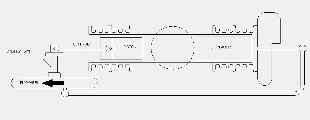
In this image then:
The displacer is at BDC
That would suggest the power piston is 90° before BDC (full expansion) moving away from the hot central section of the engine.
Defining TDC as "full compression", (minimum volume for the Power piston) with the displacer 90° ahead, (already past the same, having left TDC 90° earlier)
- Compress_20240501_141701_1561.jpg (23.07 KiB) Viewed 167 times
Of course, I suppose anyone might adjust the timing advance in whatever way they care to and perhaps the engine would still run, even if "backwards" or something.
I've put some engines through nearly the entire 360° sweep of possible displacer settings and at some point the engine will run "backwards" as if running on ice, in a reverse direction, but still run, if only barely.
On the other hand other engines may be very particular, needing almost exactly a 90° displacer advance, or won't run at all.
Anyway, in that video the displacer appears to be set to the standard 90° advance.
The shared opposed cylinder arrangement though, makes it difficult to decipher.
Slow mo:
https://youtu.be/X0XDTmcnrRg?si=GBTgD2ZB8KLd2nNT
The video can be slowed down further in the YouTube settings.
Original video:
https://youtu.be/9_dRBNi28kw?si=aCjAX6a0osU-NqHy
In this image then:
- essex.jpg (39.06 KiB) Viewed 164 times
That would suggest the power piston is 90° before BDC (full expansion) moving away from the hot central section of the engine.
Re: Isothermal Heat Transfer
I'm wondering how this arrangement would work if the displacer piston were tight fitting and the displacer chamber was open to atmosphere at the end. Kind of an opposed cylinder Alpha.
-
matt brown
- Posts: 513
- Joined: Thu Feb 10, 2022 11:25 pm
Re: Isothermal Heat Transfer
Thanks Tom. I started with same Vmin Vmax premise, but still couldn't pick up phasing until I tweaked a graphic.
I started with this past graphic, nixed regen, then made config head to head
Both graphics show distinct processes (double dwell) where head-to-head Essex appears to require 180 deg phasing mod vs common gamma. However the "drag link" reverses this back 180 deg, so phasing is per common gamma. Admittedly, the notion of compressing the hot gas does sound wild, but twice the output easy-peasy is nearly a hat trick.
I still prefer cold PP for gamma, but all gamma and beta suffer from poor torque since Pmax is PP TDC (ideal phasing). It might be a good study comparing "hot gamma" to alpha with typical out-of-phase motion. The alpha will win easily when in-phase, but out-of-phase likely lessened the difference. BTW Vincent makes a good point about Pmax at TDC is ripe for linear generator, otherwise lame.
- hot vs cold PP gamma.png (22.17 KiB) Viewed 154 times
I started with this past graphic, nixed regen, then made config head to head
- Essex vs Stirling.png (17.63 KiB) Viewed 154 times
Both graphics show distinct processes (double dwell) where head-to-head Essex appears to require 180 deg phasing mod vs common gamma. However the "drag link" reverses this back 180 deg, so phasing is per common gamma. Admittedly, the notion of compressing the hot gas does sound wild, but twice the output easy-peasy is nearly a hat trick.
I still prefer cold PP for gamma, but all gamma and beta suffer from poor torque since Pmax is PP TDC (ideal phasing). It might be a good study comparing "hot gamma" to alpha with typical out-of-phase motion. The alpha will win easily when in-phase, but out-of-phase likely lessened the difference. BTW Vincent makes a good point about Pmax at TDC is ripe for linear generator, otherwise lame.
Re: Isothermal Heat Transfer
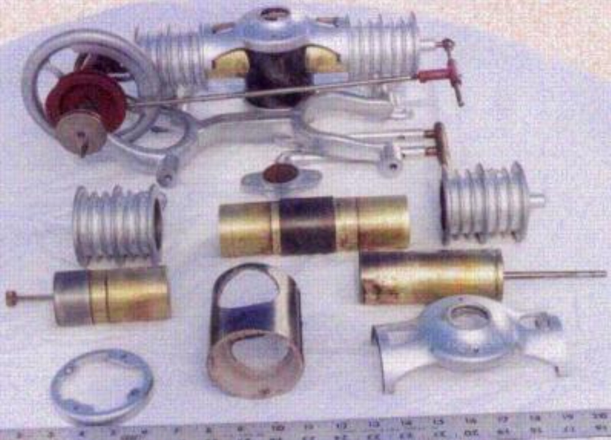
Apropos nothing, but someone might find this low res image of a part dismantled Essex twin useful useful while thinking about these engines. Gotta love that double wishbone chassis. 
Provisional dimensions subject to confirmation by Vincent
2" bore
1.2" PP stroke
2" Displacer stroke
Flywheel diameter 7.25"
Rotation anticlockwise seen from this side.
Provisional dimensions subject to confirmation by Vincent
2" bore
1.2" PP stroke
2" Displacer stroke
Flywheel diameter 7.25"
Rotation anticlockwise seen from this side.
Re: Isothermal Heat Transfer
Hopefully this video definitively shows that the displacer timing is 180 degrees behind the standard.
The crank assembly is pressed together and hasn't been modified. It is the same as all Essex engines that can be viewed on YouTube.
https://youtu.be/F3dqnWTgpWc?si=oWAuizocmAkX40yV
The crank assembly is pressed together and hasn't been modified. It is the same as all Essex engines that can be viewed on YouTube.
https://youtu.be/F3dqnWTgpWc?si=oWAuizocmAkX40yV
Re: Isothermal Heat Transfer
Thanks for adding descriptions graphics and photos of the Essex. Excellent.
Re: Isothermal Heat Transfer
I should also point out that displacer movement is "modified" from normal by the extreme rod to stroke ratio combined with displacer stroke > power piston stroke.
The original patent description has the engine spinning the other way. So I think it was designed with standard phasing in mind, but ended up running backwards.
So timing is not nearly optimized, and likely why the twin cylinder version makes much more than double the power.
The original patent description has the engine spinning the other way. So I think it was designed with standard phasing in mind, but ended up running backwards.
So timing is not nearly optimized, and likely why the twin cylinder version makes much more than double the power.
Re: Isothermal Heat Transfer
I don't know, but your video and description still sound identical to a typical LTD Gamma timing to me.VincentG wrote: ↑Thu May 02, 2024 2:38 am Hopefully this video definitively shows that the displacer timing is 180 degrees behind the standard.
The crank assembly is pressed together and hasn't been modified. It is the same as all Essex engines that can be viewed on YouTube.
https://youtu.be/F3dqnWTgpWc?si=oWAuizocmAkX40yV
When the pp is 1/2 way between BDC and TDC the displacer is all the way "down" or "over" blocking heat input, just about to move to let heat in.
When the pp is AT TDC the displacer is 1/2 on the way towards full heat exposure position.
Same basic timing in both as far as I can tell.
Re: Isothermal Heat Transfer
Tom I'd recommend you spin one of your engines by hand and take note of when the displacer fully exposes the hot plate.
Re: Isothermal Heat Transfer
I have, probably 1000 times.
Of course, you may have a different idea about what constitutes "full exposure".
An LTD displacer moving up, off a hot plate has "full exposure" almost immediately, but is still forcing air down as it rises all the way to the top of the chamber, so "full exposure" is open to some interpretation
Half way up it has only "exposed" half the gas to the hot plate and is still pushing the rest down, so I'd call that "half exposure".
Same as the Essex. Just a slightly different method of heat introduction.
Just my opinion or interpretation. How it looks to me. If you think I'm wrong, no big deal, it's your engine. I don't own an Essex.
Re: Isothermal Heat Transfer
The displacer phase angle is not subject to my opinion.