Stirling Engine Thermodynamics

Discussion on Stirling or "hot air" engines (all types)
Tom Booth
Posts: 3237
Joined: Tue Nov 07, 2006 2:03 am
Location: Fort Plain New York USA
Contact:

Re: Stirling Engine Thermodynamics

Post by Tom Booth »

In my "experiment", the engine was struggling to run because the piston had been smeared with a thick gritty paste; grinding compound, used by mechanics to get a good fit between close fitting parts, such as valves, crankshaft and connecting rod, piston and cylinder, etc.

images.jpg
images.jpg (8.34 KiB) Viewed 2045 times
Here is a video of one way it may be used to fit a piston to a cylinder, posted by a model engine builder.


https://youtu.be/w1p7C5fhZjk


The grinding compound is the primary reason that the engine was running at a very slow RPM.

It is my opinion that this additional work load may be responsible for the apparent cooling effect seen in the video, resulting in repeated re-freezing of the ice.

It was an off-hand remark and speculative hypothesis for a potential future line of inquiry and future experimentation.

The "Carnot efficiency" debate has been done to death. Please start your own thread on the subject if you like.
Nobody

Re: Stirling Engine Thermodynamics

Post by Nobody »

It will help a lot if you read the following book by Ivo Kolin:

https://www.amazon.com/gp/aw/d/09652455 ... 0965245527

Here is a Wikipedia page about the Author:

https://en.m.wikipedia.org/wiki/Ivo_Kolin

This is not a request. That book, for a person like you and I, is a must read. It appears way more expensive than when I bought it back around the turn of the millennium. Shop around, request it from a library. Read it. Senft got his start from Ivo Kolin in the 1980's. You will love it and spend hours and hours with it. It will be your goto book for discussions like this. It has many engines, indicator diagrams, and simple mathematics. And more complex mathematics. Most of it will be an easy read for most people. I appreciate the wide breath of topics it has, and have read and understood it all.

Of course if a person is "insane", it will add to it. Nicola Tesla never had a reference so good. Awesome and accurate!
Administrator
Owner
Owner
Posts: 94
Joined: Mon Jan 30, 2006 9:04 pm

Re: Stirling Engine Thermodynamics

Post by Administrator »

Mr "Nobody", please read your PM's
Administrator
Tom Booth
Posts: 3237
Joined: Tue Nov 07, 2006 2:03 am
Location: Fort Plain New York USA
Contact:

Re: Stirling Engine Thermodynamics

Post by Tom Booth »

I made the following introductory post at the very begining of this thread, more than ten years ago:
Tom Booth wrote: Tue Feb 23, 2010 6:12 pm I've been reading quite a bit about thermodynamics lately. Especially in regard to the fact that when a gas is "made to do work" it looses heat or gets cold.

This has been a hard concept for me to grasp, but apparently, when a gas does work of any kind, the heat energy in the gas is converted into "work" or the kinetic energy - such as moving a piston.

Now, formerly I had been under the impression that a Stirling engine functions by means of a temperature differential applied to it. One end of the displacer chamber is heated and the other end cooled - the air travels back and forth from one end of the chamber to the other and picks up or looses heat in that way...

But I'm becoming aware that there is also apparently something a little more subtle going on, that is, when the air in the chamber heats up and expands and then does work against the piston - the heat does not only travel to the "heat sink" at the cold end of the chamber but some of the heat is actually converted into work. In other words, what cools the hot expanding air back down is not so much, or not only coming into contact with the cold end of the chamber but heat is also lost on account of the gas being made to do work against the piston.

What I'm wondering is just how much heat is actually being absorbed in this way i.e converted into work as opposed to the heat being absorbed by the heat sink (the cold end of the chamber at ambient temperature).

If more heat is extracted as work than what actually reaches the heat sink, then theoretically, insulating the cold end of the displacer chamber against the external ambient temperatures would improve engine efficiency.

That is rather speculative, but I was also thinking that if what I have described above is true - i.e. that the heat is converted into work, then a Stirling Engine should operate cooler and be more efficient when under a heavy load doing some kind of actual work rather than just running without a load - not doing any work.

If heat is being converted into work then the more work the engine is made to perform the cooler it should run. Maybe the problem with many model Stirling engines overheating is that they are being run without a load of any kind and therefore the heat, rather than being transfered to the load on the engine to do work is just building up and causing the engine to overheat.

Perhaps this is already a known fact but for me it is something of a new realization and I'm wondering if anyone with more knowledge and experience in this area might be able to confirm or refute this supposition.

Thanks.

Tom
After ten years of additional research, study, engine building and experimentation, along with endless debate and controversy, on this and many other engineering, science, physics and "free energy" forums, I've come to the tentative conclusion that my intuitions, about how Stirling engines actually operate were correct.

Here is a simple, and hopefully easy to understand illustration.

An automobile that operates on petrol fuel, to travel up an incline, requires gas in it's tank to run the engine and overcome the downward pull of gravity.

After getting some fuel in it's tank, the car can accelerate up the hill until it runs out of gas. At that point, the engine stops, but the car may continue for a distance up the hill due to momentum. At this point the car, having spent all of it's fuel, and having used up all of it's stored momentum, stops, and unless the brakes are applied, the car will rull backwards, back down the hill to the gas pump for another refill of fuel.

Actually, due to stored momentum in accelerating back down the hill, the car will actually tend to travel further, bypassing the fuel pump. The distance it travels backward down the hill may be more than it traveled going up the hill

IMG_20211209_113846657.jpg
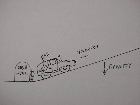
IMG_20211209_113846657.jpg (101.65 KiB) Viewed 2012 times
This is an analogy of a Stirling engine's thermodynamic cycle.

The fuel pump for the car represents the heat supply for the Stirling engine. Heat is "fuel" for a heat engine.

The gasoline in the cars gas tank represents the heat that is transfered to the Stirling engines internal "gas" or working fluid.

The car itself is the piston.

The cars engine that turns fuel into acceleration or motion is representative of the expension of the working fluid. The burning or utilization of the fuel to do work.

Gravity that the car must work against to climb the hill, represents the outside atmospheric pressure that the Stirling engine must work against to drive the piston.

IMG_20211209_113920429.jpg
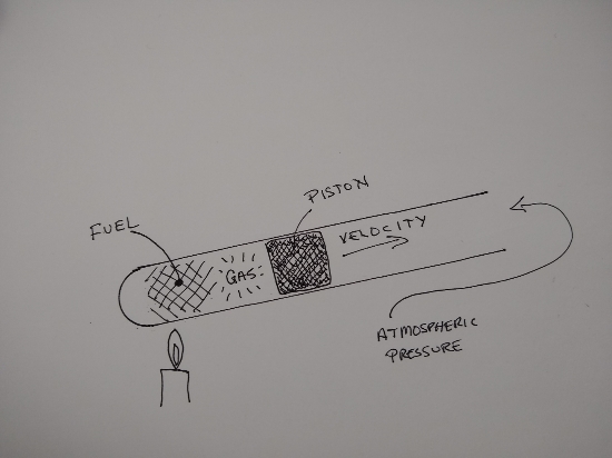
IMG_20211209_113920429.jpg (90.29 KiB) Viewed 2012 times

Perhaps this analogy is not perfect in every way, but hopefully it will help to illustrate the principle, that contrary to former concepts of how a Stirling engine operates, like a car using fuel to climb a hill, the fuel is all completely used up by the time the car runs out of gas and starts rolling backwards. The gasoline does not have to be drained out of the cars fuel tank at the top of the hill to stop the car from moving so it can roll backwards back down the hill to "complete the cycle". By the time the car reaches the top of it's climb, the fuel is already long gone. In fact due to stored momentum, it went a little further than the fuel could take it.

Likewise, in a Stirling engine, it's fuel, which is HEAT, does not need to be let out or "rejected" in order for the piston to stop, reverse course, and be pushed back down the cylinder by atmospheric pressure. The fuel/heat, that was utilized to push the piston out, has already been used up in the act of so doing.. No heat has to be removed at the end of the power stroke of the Stirling engine, just as no fuel has to be drained from the car at the top of the hill.

Now it may be, due to poor engine design, that not all the heat gets utilized and to get the car to stop and roll back down for another fill-up, half a tank of gas has to be dumped out to stop the car to allow it to roll backwards, but such wastefulness is not at all necessary, and once this is realized, better engine design is possible.
Tom Booth
Posts: 3237
Joined: Tue Nov 07, 2006 2:03 am
Location: Fort Plain New York USA
Contact:

Re: Stirling Engine Thermodynamics

Post by Tom Booth »

This video by Andrew Hall of the Stirling Engine Society was uploaded just recently:


https://youtu.be/SHyke4hUNOs


But he says, essentially, what I've been trying to get across here for the past ten years.

The "compression" stroke is also a power stroke. He doesn't really cover how exactly that is actually possible though, especially in the type of engine that runs at high speed and does not used a displacer.

IMO, how this works, as he relates in the video, the momentum in the piston results in a drop in internal pressure at the end of the expansion stroke. But I believe also, inevitably, that drop in pressure, below atmospheric pressure that allows the piston to return, by atmospheric pressure alone, without a flywheel, also results in a drop in temperature below ambient.

I would also argue that it is impossible for heat to be rejected during the compression stroke while the temperature and pressure inside the engine are lower than the temperature and pressure outside the engine.

By the time any real compression and re-heatung take place, due to the inward momentum of the piston, driven inward by atmospheric pressure, the piston is already well on its way toward TDC, so that the heat of compression, added together with the heat input, drives the temperature of the working fluid above the temperature of the heat source.

As a result, the piston is again, driven outward repeating the cycle.
Tom Booth
Posts: 3237
Joined: Tue Nov 07, 2006 2:03 am
Location: Fort Plain New York USA
Contact:

Re: Stirling Engine Thermodynamics

Post by Tom Booth »

I may be wrong, I don't know, but normally, I don't think the flame of a small lamp of the type in the video gets hot enough to melt glass.

This would seem especially true if the engine were rapidly drawing heat away to the cold end.

I've suspected, and have seen quite a bit of evidence to suggest that a Stirling engine actually tends to "send back" heat, concentrating it at the hot end, or hot side of the engine, like a heat pump.

I think, possibly there is just a bit more evidence of this phenomenon with the melted test tube in this video:

https://youtu.be/MIS11qIoM8I
Tom Booth
Posts: 3237
Joined: Tue Nov 07, 2006 2:03 am
Location: Fort Plain New York USA
Contact:

Re: Stirling Engine Thermodynamics

Post by Tom Booth »

Resize_20220928_135406_6197.jpg
Resize_20220928_135406_6197.jpg (118.26 KiB) Viewed 1601 times

During expansion, the working fluid cools providing an opportunity for limited localized heat transfer into the engine, largely blocked by the displacer. So there is already a concentration of heat in the area of the flame.

During compression, there is an additional build up of heat due to secondary heat of compression.

The temperature at the heat input site may therefore actually exceed the temperature of the heat source momentarily.

I believe it is this "collision" between heat input and the heat of compression that results in the subsequent sudden and rapid expansion during the power stroke.

I think of this as similar to a baseball pitched and hit with a baseball bat.

The energy of the pitch (compression) is added together with the energy of the swing (heat input from the heat source).

The two forces combine.

The result: a temperature high enough to melt the test tube.
Tom Booth
Posts: 3237
Joined: Tue Nov 07, 2006 2:03 am
Location: Fort Plain New York USA
Contact:

Re: Stirling Engine Thermodynamics

Post by Tom Booth »

Now I'm also wondering if the extra high heat build up near the "nose" end of this kind of engine could be the actual cause behind what happened to my foam glass displacer.
Resize_20221009_101413_3984.jpg
Resize_20221009_101413_3984.jpg (145.88 KiB) Viewed 1580 times

I had assumed it had resulted from the high temp silicone "swelling", but, I don't KNOW that.

Edit: Well, now I do:

https://www.dow.com/content/dam/dcc/doc ... elling.pdf

That report confirms:
Silicones are well known for having a large expansion when they are heated and also for their tendency to swell considerably when exposed to soluble liquids. Both volumetric expansions create pressure. (...) Silicones are known for having some of the highest coefficients of Thermal Expansion (CTE) of all elastomers
But, there was silicone along the entire length of the displacer, though possibly not as much.

There may also have been some effect due to the non-flammable lubricants, which are, I think, more water soluble than normal oil. (Yes, the "Superzilla" says: "soap and water cleanup" on the label.)

I still have a suspicion that the tip of the displacer being subject to some unusually high heat may have been a contributing factor. It seemed unaffected even by direct flame, outside the engine.

Anyway, a few lessons learned.
Tom Booth
Posts: 3237
Joined: Tue Nov 07, 2006 2:03 am
Location: Fort Plain New York USA
Contact:

Re: Stirling Engine Thermodynamics

Post by Tom Booth »

Someone on the science forums: https://www.scienceforums.net/topic/128 ... nt=1227911

had a fantastic idea that solves a long standing problem. The imperfection of any insulation that might be used to insulate the sink of a Stirling engine.
I have already sent off for one of these engines:
Resize_20230201_124711_1771.jpg
Resize_20230201_124711_1771.jpg (164.94 KiB) Viewed 1318 times
These are identical to engines I ready own for experimenting with.

The idea is to put an upright engine on top of one of these upsidedown engines with the cold side bottom (or top for the inverted engine) together, or nearly so.

Possibly both engines could share the same "bottom" cold plate.

Either the plates are chilled or ice put between or whatever, but the point being, one engine will "insulate" the other.

If the engines are REALLY behaving as some king of heat pump, pulling heat from the cold side, putting the two cold sides together solves the problem of trying to find some "Starlite" or Silica Aerogel of some such thing for insulation.

I think this should prove, or disprove something one way or the other, once and for all.
Bumpkin
Posts: 280
Joined: Fri Mar 02, 2012 1:42 pm

Re: Stirling Engine Thermodynamics

Post by Bumpkin »

Hey Tom, if the engines shared the middle plate, longer screws could bridge from hot side to hot side and eliminate the thermal short of the fasteners to the middle too.
Bumpkin
Tom Booth
Posts: 3237
Joined: Tue Nov 07, 2006 2:03 am
Location: Fort Plain New York USA
Contact:

Re: Stirling Engine Thermodynamics

Post by Tom Booth »

Bumpkin wrote: Thu Feb 02, 2023 9:50 am Hey Tom, if the engines shared the middle plate, longer screws could bridge from hot side to hot side and eliminate the thermal short of the fasteners to the middle too.
Bumpkin
Good point.

Also all the potential friction producing mechanisms would be on the hot outer sides.

I've been thinking about the necessity of there even being a middle plate.
I suppose something would need to be there to cradle some ice, cold disk or whatever, but if this cold - whatever were, say, suspended between the displacers by fishing line, another path of conduction is practically eliminated.

Regenerator? Not sure that would even be needed but probably couldn't hurt.

If the space between displacers is literally just air space or flow through "net" of fish line suspending, let's say a disk that has been dipped in liquid nitrogen, the flywheels, if there are any would need to be lashed together to keep both sides in sync.

Another configuration might be a cube made up of six engines, cold plates all towards the center.

Getting a bit further ahead. If this seems to work, which I can hardly imagine it wouldn't, at least for a while, as I've run an engine on ice continuously for 33 hours with less than perfect insulation,.. supposing there is any power output:

Have the engine(s) driving a compressor(s)

Compressing air into tubing generates heat. Use (or get rid of) the heat. That is, cool down the hot tubing.

After the heat is removed let the air in the tube escape between the engines for extra cooling, or to maintain the cold, if some heat leaks in somehow. This might only need to be done periodically to refresh the cold.

This works better and produces much colder temperatures if the air is decompressed and made to do work, in say a rotary vane air motor.

The air motor has to have a load to take the energy out of the expanding compressed and cooled gas. It (the air) leaves the air motor extremely cold. The load on the air motor can be the air compressor. A bootstrap system, so the Stirling engine(s) don't actually have to do all the work of compressing air.

What air the engine does compress releases heat that can be used to temporarily give the engine a boost of extra heat to compensate for the extra work load.

Not sure if I'm making myself clear on all this, I've had it pretty much worked out already, but the only thing puzzling me was how to find a near perfect insulation.

The guy on the science forum now says that it was a "rhetorical question" about putting the cold side of the engines together. Apparently he didn't think I would take the idea seriously. Maybe it was intended as a debunking. That is: to paraphrase;

If what you say is true, then you could put the cold side of two engines together and they would help each other.

I suppose it was intended to show me how ludicrous that would be.

Well I took it as a serious suggestion. Silly me.

I still think anyone who can entertain a possibility and come up with a theoretical solution instantly is quite a genius.

Who says there is no such thing as perfect insulation?
Tom Booth
Posts: 3237
Joined: Tue Nov 07, 2006 2:03 am
Location: Fort Plain New York USA
Contact:

Re: Stirling Engine Thermodynamics

Post by Tom Booth »

The upside down solar engine just arrived today.
Resize_20230217_174754_4363.jpg
Resize_20230217_174754_4363.jpg (186.09 KiB) Viewed 1151 times
Picked up some threaded rod as the hardware store didn't have long enough bolts the right size.
Resize_20230217_174756_6307.jpg
Resize_20230217_174756_6307.jpg (163.48 KiB) Viewed 1151 times
Not sure I'll use them, but I'll have them just In case.

I'll have my work cut out for me for a little while.

Funny, the science forum I was on where someone suggested this experiment using the two engines just banned me from the forum altogether.
Resize_20230217_180109_9383.jpg
Resize_20230217_180109_9383.jpg (100.08 KiB) Viewed 1151 times
Resize_20230217_180109_9607.jpg
Resize_20230217_180109_9607.jpg (26.34 KiB) Viewed 1151 times
I'm not really certain what I'm supposed to have done exactly
Tom Booth
Posts: 3237
Joined: Tue Nov 07, 2006 2:03 am
Location: Fort Plain New York USA
Contact:

Re: Stirling Engine Thermodynamics

Post by Tom Booth »

https://www.scienceforums.net/topic/297 ... nt=1230146

This explains the reasoning I guess, but is simply not true.

I gave a great deal of attention and consideration to everyone's comments, I even spent $60 on an inverted engine to do this follow up experiment, based on someone's suggestion. So they ban me the day the engine arrives.

Apparently having an alternative hypothesis that I would like to test experimentally before coming to any conclusions constitutes "soapboxing" and/or bad faith.

Well, when someone insists that steel bolts holding a heat engine together don't conduct heat through to the cold side, sorry, but I disagree.

Oh well.
Tom Booth
Posts: 3237
Joined: Tue Nov 07, 2006 2:03 am
Location: Fort Plain New York USA
Contact:

Re: Stirling Engine Thermodynamics

Post by Tom Booth »

For this project, I'm going to use my new LTD regenerator design in both engines.

https://youtu.be/t_0mYKcy9nE

Previously described here:

viewtopic.php?f=1&t=2690#p16204
Tom Booth
Posts: 3237
Joined: Tue Nov 07, 2006 2:03 am
Location: Fort Plain New York USA
Contact:

Re: Stirling Engine Thermodynamics

Post by Tom Booth »

Rather than bolting the two engines together, for now at least, as an alternative, I've made a plexiglass spacer with holes for clearance around the bolts and a hole cut out of the middle, for whatever initial source of cold is used to start up the engines.

Resize_20230219_143331_1700.jpg
Resize_20230219_143331_1700.jpg (150.5 KiB) Viewed 1068 times
Resize_20230219_143332_2825.jpg
Resize_20230219_143332_2825.jpg (192.4 KiB) Viewed 1068 times
Resize_20230219_143333_3020.jpg
Resize_20230219_143333_3020.jpg (162.31 KiB) Viewed 1068 times
Post Reply